- 您现在的位置:买卖IC网 > Sheet目录308 > ADP5501ACPZ-RL (Analog Devices Inc)IC LED DRVR WHITE BCKLGT 24LFCSP
ADP5501
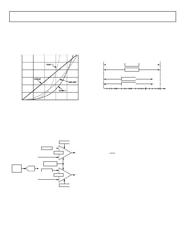
Figure 30 shows a comparison of fading techniques. Cubic fades
complete faster than linear or square fades for a given fade time
setting. Cubic 1 completes approximately 30% faster, and Cubic 2
completes approximately 10% faster, than an equivalent linear
or square fade time.
With four fade laws and 15 fade time settings, the user can
easily find the right fade experience for an application.
30
25
CUBIC 1
20
L3_CMPR is used to detect when the photosensor output drops
below the programmable L3_TRIP point. If this event occurs,
the L3_OUT status signal is set. L3_CMPR contains program-
mable hysteresis, meaning that the photosensor output must
rise above L3_TRIP + L3_HYS before L3_OUT is cleared.
L3_CMPR is enabled in Register 0x0C via the L3_EN bit. The
L3_TRIP and L3_HYS values of L3_CMPR can be set between
0 μA and 127 μA in steps of 0.5 μA (typical).
L2_TRIP
L2_HYS
15
10
LINEAR
SQUARE
L3_TRIP
L3_HYS
5
CUBIC 2
1
10
ADC RANGE (μA)
100
1000
0
0
0.2
0.4 0.6
UNIT FADE TIME
0.8
1.0
Figure 32. Comparator Ranges
The L2_CMPR and L3_CMPR comparators can be enabled
Figure 30. Fade Law Comparison over a Unit Fade Time
AMBIENT LIGHT SENSING
The ADP5501 can be used in conjunction with an external
photosensor to detect when ambient light conditions drop
below programmable set points. An ADC samples the output of
the external photosensor. The ADC result is fed into two pro-
grammable trip comparators. The ADC has an input range of
0 μA to 1000 μA (typical).
L2_EN
L2_TRIP
independently of each other. The ADC and comparators run
continuously when L2_EN and/or L3_EN is set during auto-
matic backlight adjustment mode. A single conversion takes
80 ms (typical). Filter times of between 80 ms and 10 sec can be
programmed for the comparators before they change state.
It is also possible to use the light sensor comparators in a single-
shot mode. After the single-shot measurement is completed, the
internal state machine clears the FORCE_RD bit in Register 0x0C.
The interrupt flag CMPR_INT is set in Register 0x00 if either of
the L2_OUT or L3_OUT status bits changes state, meaning that
interrupts can be generated if ambient light conditions transition
R
MP
L2
L2_HYS
_C
L2_OUT
between any of the programmed trip points. CMPR_INT can
cause the INT pin to be asserted if the CMPR_IEN bit is set in
Register 0x01. The CMPR_INT flag can be cleared only by
MP
L3
PHOTO
SENSOR
OUTPUT
ADC
FILTER
SETTINGS
L3_TRIP
L3_HYS
_C
R
L3_OUT
writing a 1 to it.
AUTOMATIC BACKLIGHT ADJUSTMENT
The ambient light sensor comparators can be used to automat-
ically transition the backlight among its three operating levels. To
enable this mode, the BL_AUTO_ADJ bit is set in Register 0x02.
L3_EN
Figure 31. Ambient Light Sensing and Trip Comparators
The Level 2 (office) light sensor comparator, L2_CMPR, is used
to detect when the photosensor output drops below the pro-
grammable L2_TRIP point. If this event occurs, the L2_OUT
status signal is set. L2_CMPR contains programmable hysteresis,
meaning that the photosensor output must rise above L2_TRIP
+ L2_HYS before L2_OUT is cleared. L2_CMPR is enabled in
Register 0x0C via the L2_EN bit. The L2_TRIP and L2_HYS
values of L2_CMPR can be set between 0 μA and 1000 μA in steps
Once enabled, the internal state machine takes control of the
BL_LVL bits in Register 0x02 and changes them based on the
L2_OUT and L3_OUT status bits in Register 0x0C. The L2_OUT
status bit indicates that ambient light conditions have dropped
below the L2_TRIP point and the backlight should be moved to
its office (L2) level. The L3_OUT status bit indicates that ambient
light conditions have dropped below the L3_TRIP point and the
backlight should be moved to its dark (L3) level. Table 5 shows
the relationship between backlight operation and the ambient
light sensor comparator outputs.
of 4 μA (typical).
Rev. 0 | Page 14 of 28
发布紧急采购,3分钟左右您将得到回复。
相关PDF资料
ADP8863ACPZ-R7
IC LED DRVR WHIT BCKLGT 20-WLCSP
ADUM1100UR
IC DIGITAL ISOL/COUPLER 8SOIC
ADUM1201CR
IC ISOLATOR DIGITAL DUAL 8SOIC
ADUM1210BRZ
IC ISOLATOR DIGITAL DUAL 8SOIC
ADUM1233BRWZ-RL
IC ISOLATR DGTL 2CH 0.1A 16-SOIC
ADUM1234BRWZ-RL
IC ISOLATR DGTL 2CH 0.1A 16-SOIC
ADUM1250SRZ-RL7
IC ISOLATOR 1MBPS 4CH 2.5K 8SOIC
ADUM1286CRZ
ISOLATOR DGTL 3KVRMS 2CH 8-SOIC
相关代理商/技术参数
ADP5501-EVALZ
制造商:Analog Devices 功能描述:SINGLE CHANNEL BOOST CONVERTER - Boxed Product (Development Kits)
ADP5520
制造商:AD 制造商全称:Analog Devices 功能描述:Backlight Driver with I/O Expander
ADP5520ACPZ-R7
功能描述:IC LED DRVR WHITE BCKLGT 24LFCSP RoHS:是 类别:集成电路 (IC) >> PMIC - LED 驱动器 系列:- 标准包装:6,000 系列:- 恒定电流:- 恒定电压:- 拓扑:开路漏极,PWM 输出数:4 内部驱动器:是 类型 - 主要:LED 闪烁器 类型 - 次要:- 频率:400kHz 电源电压:2.3 V ~ 5.5 V 输出电压:- 安装类型:表面贴装 封装/外壳:8-VFDFN 裸露焊盘 供应商设备封装:8-HVSON 包装:带卷 (TR) 工作温度:-40°C ~ 85°C 其它名称:935286881118PCA9553TK/02-TPCA9553TK/02-T-ND
ADP5520ACPZ-RL
功能描述:IC LED DRVR WHITE BCKLGT 24LFCSP RoHS:是 类别:集成电路 (IC) >> PMIC - LED 驱动器 系列:- 标准包装:6,000 系列:- 恒定电流:- 恒定电压:- 拓扑:开路漏极,PWM 输出数:4 内部驱动器:是 类型 - 主要:LED 闪烁器 类型 - 次要:- 频率:400kHz 电源电压:2.3 V ~ 5.5 V 输出电压:- 安装类型:表面贴装 封装/外壳:8-VFDFN 裸露焊盘 供应商设备封装:8-HVSON 包装:带卷 (TR) 工作温度:-40°C ~ 85°C 其它名称:935286881118PCA9553TK/02-TPCA9553TK/02-T-ND
ADP5520ACPZ-RL1
制造商:AD 制造商全称:Analog Devices 功能描述:Backlight Driver with I/O Expander
ADP5520-EVALZ
功能描述:EVAL BOARD FOR ADP5520 RoHS:是 类别:编程器,开发系统 >> 评估板 - LED 驱动器 系列:- 标准包装:1 系列:PowerWise® 电流 - 输出 / 通道:20mA 输出及类型:1,非隔离 输出电压:17V 特点:可调光 输入电压:2.7 ~ 5.5 V 已供物品:板 已用 IC / 零件:LM3508 相关产品:LM3508TLX-ND - IC LED DRVR WHT BCKLGT 9USMDLM3508TLDKR-ND - IC LED DRVR WHT BCKLGT 9MICROSMDLM3508TLCT-ND - IC LED DRVR WHT BCKLGT 9MICROSMDLM3508TLTR-ND - IC LED DRVR WHT BCKLGT 9MICROSMD
ADP5520XCPZ-R7
功能描述:IC LED DRIVER RGLTR DIM 24LFCSP 制造商:analog devices inc. 系列:* 零件状态:上次购买时间 标准包装:1
ADP5585
制造商:AD 制造商全称:Analog Devices 功能描述:Keypad Decoder and I/O Expansion GPIO functions GPIO functions
